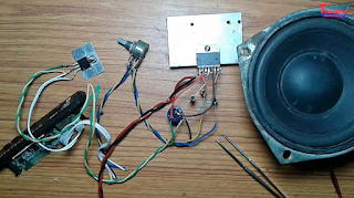
TDA7297 Ic Wiring Details
First you want this type TDA7297 ic
How To Wiring Tda7297 Ic.........??
watch this video for better understanding
This things are required to make it............
1.👉 TDA7297 audio ic board.........https://amzn.to/2AePxtr
2.👉 TDA7297 audio ic........https://amzn.to/2TdqwGn
3.👉 2 pcs 0.47uf 25 volt capacitor..........https://amzn.to/2QPHTzW
4.👉 1 pcs 2200uf 25 volt capercitor.......... https://amzn.to/2RebB0V
5.👉 1 pcs 10uf 25 volt capacitor.........https://amzn.to/2RcAzhn
6.👉 2 pcs 47k resistor.........https://amzn.to/2V0x3Wm
7.👉 1 pcs 100k dual gang potentiometer........... https://amzn.to/2Sh7bng
8.👉 Bluetooth panel......... https://amzn.to/2QNsxME
* Then you want a heat sink. Attached the heat sink with this Tda7297 ic, after applying heat sink paste back of that ic.
*Then short this pin of ic....... pin 6 - pin 7 and pin 8 - pin 9 [after watch this picture]
*This ic have 15 pin.
1 no pin........... spk out left [+]
2 no pin........... spk out left [-]
3 no pin........... Vcc
4 no pin........... Audio input left
5 no pin........... N.C.
6 no pin...........Mute
7 no pin........... Stand- By
8 no pin...........PW-GND
9 no pin...........S-GND
10 no pin........... N.C.
11 no pin........... N.C.
12 no pin........... Audio input right.
13 no pin........... Vcc
14 no pin........... spk out right [-]
15 no pin........... spk out right [+]
circuit diagram of TDA7297 ic
* This ic is stereo ic.
* This ic 30 watt ic. Per channel output 15 watt.
How to wiring........??
Watch and follow this circuit diagram for wiring this ic.
* 1 no pin........ connect speaker [+] wire [left channel] . [Connect after watch circuit diagram]
* 2 no pin........ connect speaker [-] wire [left channel]. [Connect after watch circuit diagram]
* 3 no pin........ short with pin no 13. (for Vcc). [Connect after watch circuit diagram]
* 4 no pin........ connect 0.47uf capacitor. Then input audio second side of capacitor.[Left channel]
* 5 no pin........ for N.C. [you can leave this pin]
* 6 no pin........short with pin no 7. [Connect after watch circuit diagram]
* 7 no pin........after shorting pin 6 with pin 7 connect 2 pcs 47k resistor and 1 pcs 10uf resistor. then 1 pcs 47k resistor and 10uf capacitor connect in GND. and second 47k resistor connect with Vcc(13 no pin). [Connect after watch circuit diagram]
* 8 no pin........connect GND.
* 9 no pin........connect GND.
* 10 no pin........ for N.C. [you can leave this pin]
* 11 no pin........ for N.C. [you can leave this pin]
* 12 no pin........ connect 0.47uf capacitor. Then input audio second side of capacitor.[Right channel]
*13 no pin..........this pin is voltage input pin. so connect 2220uf capacitor on pin no 13 and also connect capacitor [-] with GND.
* 14 no pin........ connect speaker [-] wire [Right channel]. [Connect after watch circuit diagram]
* 15 no pin........ connect speaker [+] wire [Right channel]. [Connect after watch circuit diagram]


3 Comments
Bhai issme kitne amo ki supply dene hai agar hum 20 watt ka speaker use kre iss apmlifier board m
ReplyDeleteBhai tv ka pcb mein audio section ka board mein kaise power input,audio input aur volume control ka connection kar na hein plz bata do
ReplyDeleteCheckout my article for Connection
ReplyDeleteeasyamplifier.com/tda7297