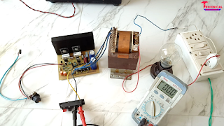
100 watt mono amplifier using 2×2SC5200
Components►
1. 2×2SC5200 Transistor.
2. 1×TIP41 Transistor.
3. 2×TIP42 Transistor.
4. 2×C2229 Transistor.
5. 2×A1015 Transistor.
6. 2×100uF capacitor 50/63V.
7. 1×2.2uF capacitor 50/63V.
8. 2×10pF capacitor 50/100V.
9. 2×10²pF capacitor 50/100v.
10. 1×0.1uF/104pF capacitor 100/250V.
11. 2×0.33Ω resistor 5w.
12. 1×10Ω resistor 2w.
13. 2×100Ω resistor 1w.
14. 1×10Ω resistor 1w.
15. 1×4.7kΩ resistor 1w.
16. 2×10Ω resistor 1/2w.
17. 1×33Ω resistor 1/4w.
18. 3×150Ω resistor 1/4w.
19. 1×1kΩ resistor 1/4w.
20. 1×10kΩ resistor 1/4w.
21. 2×68kΩ resistor 1/4w.
22. 1×33kΩ resistor 1/4w.
23. 2×3.3kΩ resistor 1/4w.
24. 3×1N4007 diode.
25. 1×Zener 24 volt 1w.
26. 4×6A4T diode.
27. 2×4700uf capacitor 50V.
Watch this video for better understanding
License► ©Technical Mriganka. You can't use this pcb layout for commercial purpose. You can use this pcb layout only for educational and diy projects.
PCB LAYOUT►https://drive.google.com/file/d/10nix7IZqZ_zYO_Ug_VTk4yOiHKsxRWbS/view?usp=drivesdk
In this post I make a 100 Watts R.M.S amplifier using 2×2SC5200 Transistor. Which can deliver upto 100 Watts in R.M.S power at 8Ω. We test this amplifier, and we got it's frequency range 40hz-20khz. For power supply you can use 30-0-30V 5A transformer. Now follow my steps for this amplifier. First we make pcb. For make pcb you need pcb layout. download the pcb layout and print it by laser printer on photo paper. Then cut the pcb layout. Then press the pcb layout by iron on copper clad board. Press the iron 10-15 munites. Then leave the pcb for cool down 10 munites. when the pcb was cool, put the pcb in water and move the pcb layout to copper clad board. Then put the pcb in ferric chloride [FeCl3+H2O] for etching 10-15 munites. when etching was end, clean the pcb by water. Then make hole on pcb. And then press the upper side print of pcb. Now your pcb is ready mount components by instruction.
In this post I make a 100 Watts R.M.S amplifier using 2×2SC5200 Transistor. Which can deliver upto 100 Watts in R.M.S power at 8Ω. We test this amplifier, and we got it's frequency range 40hz-20khz. For power supply you can use 30-0-30V 5A transformer. Now follow my steps for this amplifier. First we make pcb. For make pcb you need pcb layout. download the pcb layout and print it by laser printer on photo paper. Then cut the pcb layout. Then press the pcb layout by iron on copper clad board. Press the iron 10-15 munites. Then leave the pcb for cool down 10 munites. when the pcb was cool, put the pcb in water and move the pcb layout to copper clad board. Then put the pcb in ferric chloride [FeCl3+H2O] for etching 10-15 munites. when etching was end, clean the pcb by water. Then make hole on pcb. And then press the upper side print of pcb. Now your pcb is ready mount components by instruction.
After complete the amplifier, don't forget to series light test. If light glow, then understand the amplifier not work properly. Check the amplifier properly and find out problem. And if the light doesn't glow then check the following voltages.
Speaker output voltage► 0.0 volt (without signal)
Baising voltage► 0.5-0.7 volt.
Audio input voltage► 0.0 volt
If you get same voltages, your amplifier is ready. Now connect speaker and input preamplifier.


5 Comments
Price of this complete board
ReplyDeletepcb size kitne by kitne
ReplyDeletePcb size kyu nahi dete men to pcb hai nahi to pura video west hai
ReplyDeletebhaiya maine bhi same board banaya hoon... magar wo TIPC thoda heat ho raha hai .. baki sab kuch masgt chal raha hai.. thank you bhaiya :)
ReplyDeleteBhai board kitne RS m banker tiyar huaa h
Delete