components ᐅ
1. LM3886TF ic.
2. 3×1kΩ resistor 1/4W.
3. 3×22kΩ resistor 1/4W.
4. 2×10Ω resistor 1W.
5. 3×0.1uF (104) capacitor 100V.
6. 1×22uF capacitor 63V.
7. 1×2.2uF capacitor 63V.
8. 2×4700uF capacitor 35V.
8. 1×5uH coil (1mm/ 19 gauge copper wire)
9. 1×2 pin screw terminal.
10. 1×3 pin screw terminal.
11. 1× Bridge Rectifier GBU1508/ GBU808
12. 1×2 pin connecter base 2.54 mm.
License► ©Technical Mriganka. You can't use this Pcb Layout and Gerber File for commercial purpose. You can use this pcb layout and gerber file only for educational and diy projects.
How to order PCB at PCBWay.com
First Search on Google 'PCBWay'. Then go to pcbway.com
On PCBWay you can get 100x100mm 2 Layer Pcb only at $5. Maximum size pcb you can get 500x1100mm. And maximum Layer is up to 14 Layers.
Then click on - 'Sign in | Join'
After fill up Delivery Address, again go to home page of PCBWay.com. Then click on 'Quote Now'
Now here you choose your PCB option.
After choose your PCB option click on 'Calculate'. Then choose your country and shipping method. And then click on 'Save to Cart'.
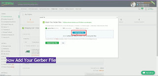
Now add your Gerber File, and then click on 'Submit Order Now'.
After 10 minutes (approx) you will get a message. On the message you will know, your pcb approved or not.
If your pcb approved, reload the page. And then click 'Proceed to Checkout'.
Now select 'Payment Methods' and then Pay.
Specification ᐅ
68W Output Power into 4Ω at VCC = ±28V
38W Output Power into 8Ω at VCC = ±28V
50W Output Power into 8Ω at VCC = ±35V
135W Peak Output Power. Signal-to-Noise Ratio ≥ 92dB
38W Output Power into 8Ω at VCC = ±28V
50W Output Power into 8Ω at VCC = ±35V
135W Peak Output Power. Signal-to-Noise Ratio ≥ 92dB
How to make PCB by ironing method ᐅ
For make PCB you need PCB layout. download the PCB layout and print it by laser printer on photo paper. Then cut the PCB layout. Then press the PCB layout by iron on copper clad board. Press the iron 10-15 minutes. Then leave the PCB for cool down 10 minutes. When the PCB will cool, put the PCB in water and move the PCB layout to copper clad board. Then put the PCB in ferric chloride [FeCl3+H2O] for etching 10-15 minutes. when etching was end, clean the PCB by water. Then make hole on PCB. And then press the upper side print of PCB. Now your PCB is ready, mount components by instruction.
Watch This video for how to make Pcb by ironing method
How to test this amplifierᐅ
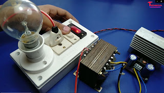
After complete this board don't forget to series light test.
When you will on this amplifier via series light, it glow for some time (1 - 2 sec). Then series light will turned off fully. If the series light will fully turned off, then check the voltages.
Then check Speaker Output and Audio Input voltage. Here you get no voltages 0.00V. If you get same voltages, then connect preamplifier to input and connect speaker to output.


3 Comments
Circuit diagram
ReplyDeleteDear Sir,
ReplyDeleteI am based in MUMBAI, INDIA.
LM 3886 - I want to have this board or fully assembled board
Kindly let me know your number or please call on my number: 9769 484 123
Thanks
Bird Kumar
want the inductor as shown in the video, how many turns and diameter should I wrap, I don't have vom. thanks
ReplyDelete