
Diy 70 watts amplifier using TDA2050 ic

This things are required to make it.........

For circuit diagram
*👉All resistor 1/4 watt.
1.👉 2 pcs TDA2050 ic............https://amzn.to/2BGiAa5
2.👉 4 pcs 22k resistor............https://amzn.to/2UTIZZ8
3.👉 2 pcs 560E resistor...........https://amzn.to/2IdWwJu
4.👉 2 pcs 2.2E resistor.............https://amzn.to/2BDHpTZ
5.👉 2 pcs 1uf capacitor.............https://amzn.to/2V1OJ3b
6.👉 2 pcs 22uf capacitor............https://amzn.to/2ByjW6z
7.👉 4 pcs 470uf capacitor...........https://amzn.to/2V17J1O
8.👉 2 pcs 0.47uf/473pf/470nf capacitor.
Other components
1.👉 Bluetooth module...........https://amzn.to/2BEu1zc
2.👉1 pcs the 100k dual gang potentiometer..........https://amzn.to/2GsMJxK
3.👉 1 pcs 7805 voltage regulator ic............https://amzn.to/2BBpjCj
4.👉1 pcs 12-0-12 volt 3 ampere transformer.

circuit diagram
Diy 70 watts amplifier using TDA2050 ic, hindi. Technical Mriganka.
watch this video for better understanding
*Watch this circuit diagram and follow my steps for make it.

*First you want 2 pcs TDA2050 ic. 1 TDA2050 ic is 35 watts. We use here 2 pcs TDA2050 ic, so we can get 70 watts output easily.
TDA2050 ic pin out.........
*1 no pin.........non inverting input.
*2 no pin.........inverting input.
*3 no pin ........[-vs] negative voltage input.
*4 no pin.........output for speaker.
5 no pin...........[+vs] positive voltage input.

*Then yow want this type vero board / 0 pcb.

*Then solder ic's pin with vero board.

*Then short ic's 2 no pin to 4 no pin by 22k resistor. [connect after watch circuit diagram].
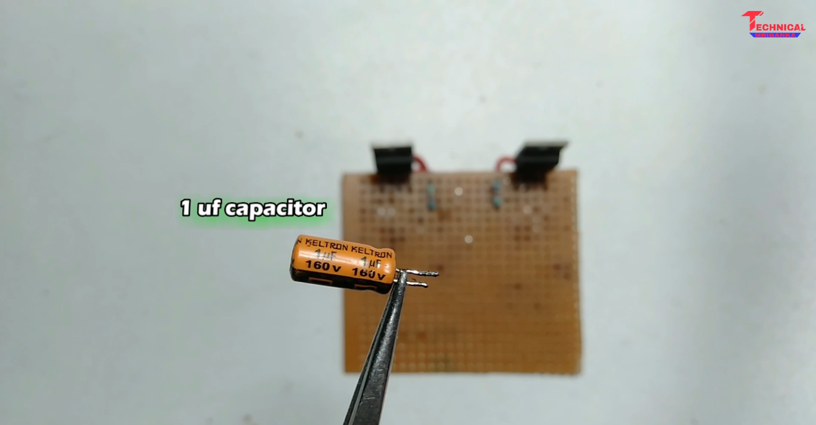
*Then you want 1uf capacitor. connect this capacitor on ic's 1 no pin. [connect after watch circuit diagram].

*Then you again want 22k resistor. connect this resistor on ic's 1 no pin. [connect after watch circuit diagram].

*Then you want 560 ohm resistor. connect this resistor on ic's 2 no pin. [connect after watch circuit diagram].

*Then you want 22uf capacitor. connect capacitor [+] with 560 ohm resistor, and connect capacitor [-] with gnd [connect after watch circuit diagram].

*Then short 22k (1 no pin) resistor with 22uf capacitor [-] pin. And here create GND. [connect after watch circuit diagram].

*Then connect 470uf capacitor [-] pin with ic's 3 no pin, and connect capacitor [+] pin with GND.
[connect after watch circuit diagram].

*Then connect 2.2 ohm resistor on ic's 4 no pin.

*Then you want 0.47uf capacitor. Connect 0.47uf capacitor [+] pin with 2.2 ohm resistor and capacitor [-] pin connect with GND.

*Then connect 470uf capacitor [+] pin with ic's 5 no pin, and capacitor [-] pin connect with GND. [connect after watch circuit diagram].

*Then you want 2 pcs 2200uf capacitor. connect and soldier this capacitor with vero board.

*Then short 2 TDA2050 ic's 3 no pin by wire, and connect the wire where 2200uf capacitor [-] pin is connected. [connect after watch circuit diagram].
*Then short 2 TDA2050 ic's 5 no pin by wire, and connect the wire where 2200uf capacitor [+] pin is connected. [connect after watch circuit diagram].
*Then short 2 TDA2050 ic's GND pin by wire, and connect the wire where 2 pcs 2200uf capacitor [+] and [-] pin is connected. [connect after watch circuit diagram].

*Then you want 100k dual gang potentiometer, bluetooth module, speaker connector, 3 ampere 12-0-12 volt transformer.
*Connect the 100k dual gang potentiometer output wire with ic's 1uf capacitor, where audio input. And connect 100k dual gang potentiometer input wire with bluetooth module or any audio source.
*Then connect the speaker connector socket with ic's 4 no pin where spk out.
*Then connect transformer with this amplifier. [connect after watch circuit diagram].
*Now play it.
Thank you,
Technical Mriganka...........


0 Comments