TEA2025B ic audio amplifier made with 4 volt battery
1.👉 TEA2025B ic..............https://amzn.to/2VdWcx6
2.👉 2 pcs 470uf capacitor................https://amzn.to/2BMNyfM
3.👉 6 pcs 100uf capacitor.................https://amzn.to/2GLIBtA
4.👉 2 pcs 223pf capacitor................https://amzn.to/2QZodtS
5.👉 Bluetooth module................https://amzn.to/2BMZrmb
6.👉 1pcs spst switch.................https://amzn.to/2BMpZDW
7.👉 1pcs dc socket..................https://amzn.to/2GLJbHM
8.👉 1pcs speaker clip connector...............https://amzn.to/2Vcwcly
Watch This Video For Better Understanding
*TEA2025B ic pinout........
1 no pin...........Bridge
2 no pin...........Out.2
3 no pin...........Boot.2
4 no pin...........Gnd
5 no pin...........Gnd
6 no pin...........Feedback
7 no pin...........Audio input
8 no pin...........Svr
9 no pin...........Gnd
10 no pin...........Audio input
11 no pin...........Feedback
12 no pin...........Gnd
2 no pin...........Out.2
3 no pin...........Boot.2
4 no pin...........Gnd
5 no pin...........Gnd
6 no pin...........Feedback
7 no pin...........Audio input
8 no pin...........Svr
9 no pin...........Gnd
10 no pin...........Audio input
11 no pin...........Feedback
12 no pin...........Gnd
13 no pin...........Gnd
14 no pin...........Boot.1
15 no pin...........Out.1
16 no pin...........3-15 volt dc input.
circuit diagram of TEA2025B ic
* This ic is stereo ic.
* This ic is 10 watt ic. Per channel output 5 watt.
*Now watch the circuit diagram and follow my steps to make amplifier.
*First you need a plastic case for assemble this amplifier.
*Then cut the plastic case size of the bluetooth module. And input the bluetooth module after cut the plastic case.
*Then attached the TEA2025B ic with the heat sink, after applying heat sink paste between heat sink and TEA2025B ic. And make a hole on the plastic case. then input the TEA2025B ic on plastic case.
*Then connect 470uf capacitor [+] pin with ic's 2 no and 15 no pin. And capacitor [-] pin is speaker output.
*Then short ic's 3 no and 14 no pin by 100uf capacitor. [connect after watch circuit diagram]
*Then short all gnd pin of ic. Short ic's 4, 5, 9, 12, 13 no pin by a wire.
*Then connect 100uf capacitor [+] pin with ic's 6, 8 and 11 no pin. and capacitor [-] pin connect with gnd.
*Then connect 223pf capacitor with ic's 7 and 10 no pin. And here is audio input.
*Then connect the gnd wire with 1000uf (power) capacitor [-] pin. and connect it 4 volt battery's [-] pin.
*Then you need a dc socket for charge the 4 volt battery. Connect IN4007 diode with the dc socket as well as the picture.
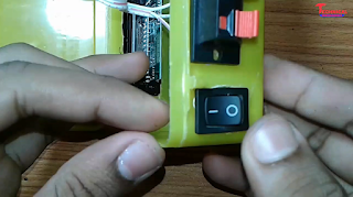
*Then you need a spst switch. Make a hole on plastic case and input the switch.
*Then connect wire on ic's 16 no pin and connect it with spst switch's first pin and second pin is connect with 1000uf (power) capacitor [+] pin. And then capacitor [+] pin wire connect with 4 volt battery's [+] pin.
*Then connect wire on dc socket. IN4007 diode's [-] pin is connect with 4 volt battery's [+], and dc socket's gnd pin is connect with 4 volt battery's [-] pin.
*Now your circuit is ready. play songs on this circuit.
Thank you,
Technical Mriganka...........


0 Comments