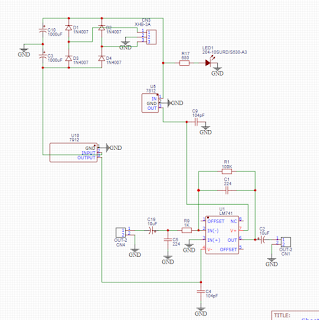
components ᐅ
1. 1×UA741/ TL071/ TL081 IC.
2. 1×1KΩ resistor 1/4W.
3. 1×100KΩ resistor 1/4W.
4. 1×680Ω resistor 1/4W.
5. 2×0.22uF (224) capacitor 50/100V.
6. 2×0.1uF (104) capacitor 50/100V.
7. 2×10uF capacitor 25/50/63V.
8. 2×1000uF capacitor 25V.
9. 4×IN4007 Diode.
10. 2×2 pin connecter base/ socket 2.54 mm.
11. 1×3 pin connecter base/ socket 2.54 mm.
12. 1×47K/ 100K single turn potentiometer.
13. 1×8 pin IC base/ socket.
14. 1×7815/7812 + voltage regulator.
15. 1×7915/7912 - voltage regulator.
16. 1×3 mm Led.
License► ©Technical Mriganka. You can't use this PCB Layout and Gerber File for commercial purpose. You can use this PCB layout and Gerber file only for educational and DIY projects.
Specification►
In this post I make a Bass booster for subwoofer, using 741 IC. you can also use here TL071, TL081 IC. Frequency response 60Hz - 120Hz. For power supply you can use 12-0-12V 500mA/750mA transformer.
In this post I make a Bass booster for subwoofer, using 741 IC. you can also use here TL071, TL081 IC. Frequency response 60Hz - 120Hz. For power supply you can use 12-0-12V 500mA/750mA transformer.
How to make PCB by ironing method ᐅ
For make PCB you need PCB layout. download the PCB layout and print it by laser printer on photo paper. Then cut the PCB layout. Then press the PCB layout by iron on copper clad board. Press the iron 10-15 minutes. Then leave the PCB for cool down 10 minutes. When the PCB will cool, put the PCB in water and move the PCB layout to copper clad board. Then put the PCB in ferric chloride [FeCl3+H2O] for etching 10-15 minutes. when etching was end, clean the PCB by water. Then make hole on PCB. And then press the upper side print of PCB. Now your PCB is ready, mount components by instruction.
For make PCB you need PCB layout. download the PCB layout and print it by laser printer on photo paper. Then cut the PCB layout. Then press the PCB layout by iron on copper clad board. Press the iron 10-15 minutes. Then leave the PCB for cool down 10 minutes. When the PCB will cool, put the PCB in water and move the PCB layout to copper clad board. Then put the PCB in ferric chloride [FeCl3+H2O] for etching 10-15 minutes. when etching was end, clean the PCB by water. Then make hole on PCB. And then press the upper side print of PCB. Now your PCB is ready, mount components by instruction.
How to test this amplifierᐅ
Check audio input and audio output. Here you get no voltage 0.00V. If you get 0.00V, then connect it to amplifier.


0 Comments